Equipment Upgrade 2002
Introduction
Our original system, designed in 1998, is described on our main page, and in the technical details section. It was a low budget system that worked well and allowed our entrance into this interesting field. Spurred by increased interest, and a little more pocket money, we launched a major upgrade that is described here.
Antenna
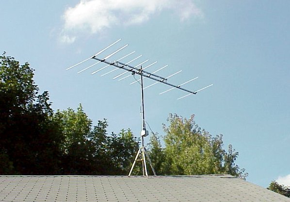
We improved the antenna system described on our main page. Our new antenna is a Winegard HD6065P High Definition FM Antenna. You can view the datasheet and the directional patterns as a PDF file here As the photograph shows, it's a beautiful sight when it's finally placed.
Note the precautions required for antenna installations, and please read our disclaimer. Antenna instructions are included with the antenna, the rotor, and with your FM receiver. The worst hazard is from electrical shock in contacting nearby electrical wires. Keep the antenna well away from any electrical wires! Also, the antenna and mount should be grounded. Follow the grounding instructions carefully. Both the RF lead and antenna mount are grounded. Then, there's the other hazard of falling off the roof! We used a GC Waldom tripod (three foot), as shown below, and bought a coaxial ground block, ground wire, and a ground rod at Radio Shack. Antenna amplifiers are never needed, so save your money.

Home antenna rotators are fairly standard. Our original system used a Radio Shack rotator, but the present system used a very similar one from NTE Electronics (U-105). Although amateur radio rotators have an angle sensor and a feedback circuit to allow precise angular positioning, home rotors use a less expensive approach. There's a 1 RPM motor in the control box that matches the 1 RPM motor of the rotator assembly. When these are synchronized by going to the limit of travel (i.e., setting the antenna North), they're fairly accurate. You can buy these rotators in many places, including Radio Shack, but I think they may all be manufactured by the same company.
Computer Interface
The schematic diagram for the computer interface circuitry is shown below. Since most meteor events are fast, the circuit has a peak detector to capture the peak and hold it for a few seconds. The circuit needs only a single five volt power source, since it uses rail-to-rail operational amplifiers, and the LTC1298 works with five volts also. Since the parallel port signals are TTL level, which is five volts, it's one big happy family! The LTC1298 is a two channel device, so we put the raw signal with no peak detection in the second channel since we had it. This is useful for setup, but it's superfluous to the operation.
We put the circuit inside our FM tuner. The FM tuner had a ten volt power supply, so we used a five volt voltage regulator. When you do this sort of thing, you should be confident that there's enough power to go around. Of course, the tuner needs to have a signal strength meter you can tap, or you need more circuitry. The additional circuitry (essentially an RF to DC converter taken from the last IF stage) is not that hard to design and build, but we didn't get into that.
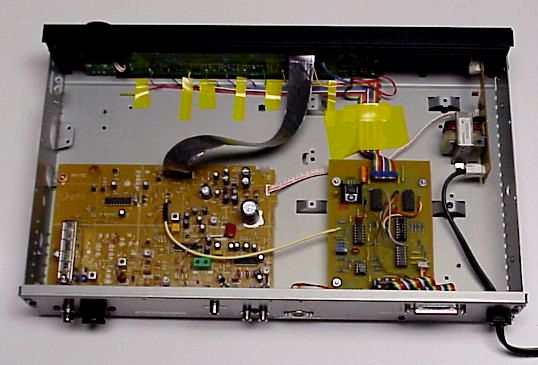
A phtograph of our FM tuner interior with our added circuit board is shown below. The entire FM tuner is on the large board to the left, and our circuit is on the right. Our board contained some additional circuitry to control the front panel switches. That's why there's a ribbon cable to the front panel. See the technical details page for hints and cautions.
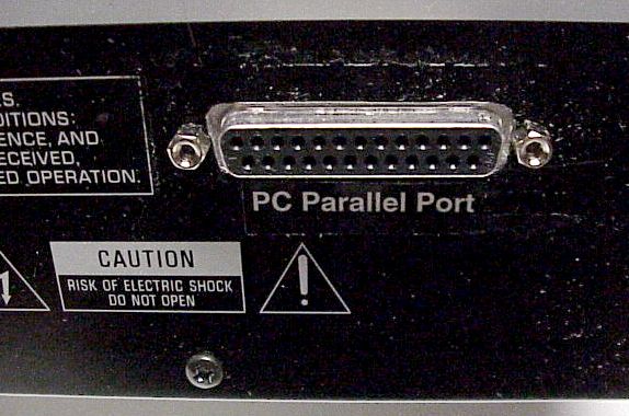
Here's a photograph of the parallel port connector we put on the rear panel of the FM tuner. Note the caution label below it. If you're not a certified electronics technician, don't try modifications like this yourself! Amateur radio operators (Hams) are knowledeable people, and they are usually very helpful. You can use the the American Radio Relay League web site to find some in your area.
Software
We've used Microsoft Visual Basic, version 3.0, for many years. We've never upgraded (it's at version 6.0, now), but it serves us well for our simple tasks. The analog to digital converter interfaces to the computer via the parallel (printer) port. The circuit was designed to be compatible with the older, uni-directional, printer ports, but all computers nowadays have bidirectional ports. Visual Basic itself cannot communicate with the parallel port, but some enterprising people wrote a DLL ( inpout.dll) to accomplish this task. The essential source code is found here. It took us a while to get this working, so don't expect too easy a run! The logic behind the code can be found in the LTC1298 datasheet. This can be found at the Linear Technology web site here. This is a popular circuit, so there's a lot of information about it on the web.
Return to main page
Comments and technical questions can be addressed to Devlin Gualtieri, at Honeywell Laboratory, Morristown, NJ.