Antennas
May 16, 2016
The term, "antenna," is understood in different ways by different people. The
biologists among us would likely think of
arthropod antennas that are used to sense airborne
molecules, such as
pheromones.
Engineers, however, will think of
radio antennas used to couple
electromagnetic waves to
electronic circuitry. This article is about the
radio engineer's antenna.
As a
child of the
space age, I enjoyed looking at
photographs of antennas. Most space antennas were huge, a fact that appealed to one who enjoyed reading books about
dinosaurs. Quite unlike the straight
rod automobile antenna, the space age antennas had unusual shapes that appealed to their
mystery. The
iconic antenna of the early space age was the
Jodrell Bank radio telescope antenna, now called the
Lovell Telescope in honor of its creator,
Bernard Lovell (1913 - 2012).
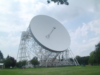
(Photo by Matt Buck, via Wikimedia Commons.)
The principal purpose of an antenna is to
efficiently convert the electromagnetic radiation present in
free space to an
electrical current. We're aided by the fact that the
impedance of free space is about 375
ohms, which, as
Goldilocks would say, is neither too high nor too low. Its value is exactly equal to the product of the
permeability of free space and the
speed of light; that is 119.9169832π.
The original Jodrell Bank antenna has a diameter of 250
feet, and the reason for its huge size and the size of its radio telescope cousins is the desire to collect as much radiation as possible from faint
extraterrestrial radio sources in a very
narrow beam. When receiving
terrestrial signals of higher
power, the size of the antenna can be made smaller; smaller, that is, up to a point.
Antennas will operate efficiently only if their dimension is at least a large fraction of the
wavelength of the electromagnetic radiation they are designed to detect. That's why the antennas of AM radio stations are huge
towers, more than a hundred meters high. In contrast, wireless routers have antennas just a few centimeters long. That's because
Wi-Fi signals of 2.45 and 5.2 GHz have wavelengths of just 12 cm and 6 cm, respectively.
For signals in the VHF band, such as
FM radio stations, the most popular antenna type is the
Yagi-Uda antenna, generally called just a Yagi antenna in the United States, since
Hidetsugu Yagi published the concept in English, while Shintaro Uda only published in Japanese. Yagi also had a 1932 US patent for this antenna.[1]
The Yagi-Uda antenna is directional. In radio parlance, it offers
gain over the isotropic; that is, it enhances sensitivity in one direction, at the same time rejecting
noise at angles away from that direction. It accomplishes this using
phase interference.
Schematic diagram of a Yagi-Uda antenna.
(Drawn using Inkscape)
In the figure above, the reflector element is spaced a quarter of a wavelength from the driven element. This leads to constructive interference for waves in the forward direction, and a lesser signal at other angles. The director elements likewise re-radiate energy they receive in a way that enhances the signal of the driven element in the forward direction and diminishes the
radiation in other directions. An important variation of the Yagi-Uda antenna is the
log-periodic antenna, which is essentially a combination of Yagi-Uda antennas of different frequency connected together.[2]
The driven element of the Yagi-Uda antenna is a
dipole, a simple antenna type that operates without the reflector and director elements. A lone dipole receives signals over a wide range of angles (see figure). The
transmitting antenna, used by Heinrich Hertz in his 1887 demonstration of radio transmission and detection, was a dipole.
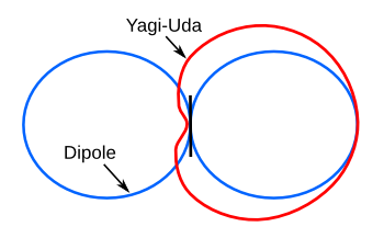
Relative reception patterns of a dipole and Yagi-Uda antenna.
A greater number of elements will sharpen the Yagi-Uda pattern.
(Drawn using Inkscape.)
The reflector principle can be applied to a simple antenna type called a bowtie antenna, named after its similarity to a
bowtie. This antenna type is common today for the reception of
digital television. In areas of high signal strength of the broadcast signals, such as
metropolitan areas, these can be mounted on an interior wall.
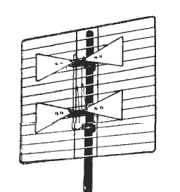
A bowtie antenna.
The grill reflector and multiple dipoles give directivity, and the shaped dipoles give wide bandwidth.
(Modified Wikimedia Commons image.)
My favorite antenna type is the
axial mode (end fire) helical antenna, invented in 1946 by
John Kraus (1910-2004). Kraus described the dimensions of his prototype antenna in his classic
textbook, "Antennas."[3] The
helix was seven turns of
copper wire with a 12
centimeter circumference, this being the wavelength of his
signal source (2.5 GHz). Helical antennas are used in many
high frequency applications, such as
satellite communication (see figure).
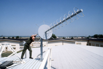
A satellite communications antenna pictured in 1984.
This is a typical helical antenna.
(US Air Force photograph by SSgt Louis Comeger, via Wikimedia Commons.)
There's an interesting
anecdote from Kraus'
university career. When constructing a
large radio telescope from multiple helical antennas,[4] Kraus needed a small building to hold the
receiving equipment. Knowing that the university
bureaucracy would preclude speedy construction of even such a small structure, perhaps even preventing it, he and a
graduate student built it themselves. When the building was eventually discovered by the
university administration, they wondered how he was able to do this. Said Kraus, "...When I
requisitioned material, I said it was for a receiver
enclosure, which it was. It was a really appropriate description. And we got the job done."[5]
I wrote about
fractals in a
recent article (The Fractal Author, February 22, 2016). After
Benoit Mandelbrot's popularized this
geometrical object in his 1982 book,
The Fractal Geometry of Nature, it was just a matter of time before this geometry was tried as a
fractal antenna (see figure). This antenna type seems to have a small advantage over others in small devices, such as
RFID tags and
cellphones.
Figure 7E of US Patent No. 6,452,553, "Fractal antennas and fractal resonators," by Nathan Cohen, September 17, 2002.
Engineers will notice the resemblance to a twin-lead "T" antenna.
(Via Google Patents.)[2])
Just in the news was the detection of
gravitational radiation by the
Laser Interferometer Gravitational-Wave Observatory (LIGO).[7] After reading about the
complexity of this detection, it's surprising that it might be possible to detect such radiation using an antenna. In this case, the detection would be of
primordial gravitational waves generated just a small fraction of a second after the
Big Bang.[9]
These waves should make themselves known through a “swirl” in the
polarization of the
cosmic microwave background radiation, something thought to have been detected in 2014 by the
South Pole–based BICEP2 experiment, but the detection was found to be an
artifact of
dust in our
Milky Way Galaxy.[9]
The trick to preventing an error such as that in the BICEP2 experiment is to make measurements at multiple
frequencies. The BICEP2 detectors were tuned for just 150
GHz, but measurement at multiple frequencies would allow subtraction of the
interfering galactic emission. The proposed antennas for this new measurement are
superconducting sinuous antennas made from
niobium. The sinuous antenna is a fractal antenna, and the fractal nature of its structure allows detection of radiation over a wide band.[9]
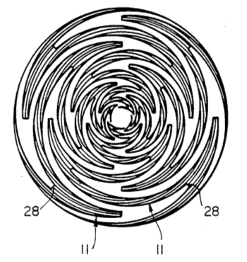
A sinuous antenna.
Fig. 7A of US Patent No. 4,658,262, "Dual polarized sinuous antennas," by Raymond H. DuHamel, April 14, 1987.
(Via Google Patents.)
The sinuous antennas developed for the cosmic microwave background observations are augmented by a
silicon lens. The smallest feature size of the antenna is about a
micrometer, and the entire antenna, with lens, is about 5
millimeters across.[9] The experiment will be conducted at the
Atacama Desert site that hosts the
Atacama Large Millimeter Array. This site, at 5,000 foot
altitude in a
dry climate, is ideal for detection of high frequency signals usually attenuated by
water vapor in the
atmosphere.
References:
- Hidetsugu Yagi, "Variable Directional Electric Wave Generating Device," US Patent No. 1,860,123, May 24, 1932.
- Raymond H. Du Hamel and Fred R. Ore , "Logarithmically periodic rod antenna," US Patent No. 3,079,602, February 26, 1963.
- J.D. Kraus, "Antennas," McGraw-Hill (New York, 1988), 265 pp., via Amazon).
- John Kraus, "Big Ear," Cygnus-Quasar Books (Powell, Ohio, 1976).
- Robert W. Wagner, "Interview of John Daniel Kraus," Ohio State University, University Archives Oral History Program, Ohio State University Oral History Project, 2005.
- Benoit B. Mandelbrot, "The Fractal Geometry of Nature," W. H. Freeman and Company, 1982, ISBN-13: 978-0716711865 (via Amazon).
- Nathan Cohen, "Fractal antennas and fractal resonators," US Patent No. 6,452,553 , September 17, 2002.
- Gravitational Waves Detected 100 Years After Einstein's Prediction, California Institute of Technology Press Release, February 11, 2016 .
- Rachel Courtland, "Swirly Antennas Will Hunt for the Twists of Ancient Gravitational Waves," IEEE Spectrum, March 23, 2016.
- Raymond H. DuHamel, "Dual polarized sinuous antennas," US Patent No. 4,658,262, April 14, 1987.
Permanent Link to this article
Linked Keywords: Biologist; arthropod; antenna; molecule; pheromone; engineer; radio antenna; electromagnetic radiation; electromagnetic wave; electronics; electronic circuitry; radio engineer; child; space age; photograph; dinosaur; rod; automobile; mystery; cultural icon; iconic; Jodrell Bank Observatory; radio telescope; Lovell Telescope; Bernard Lovell (1913 - 2012); radar; booster rocket; Sputnik 1; artificial Earth satellite; Wikimedia Commons; energy conversion efficiency; vacuum; free space; electrical current; impedance of free space; ohm; Goldilocks and the Three Bears; vacuum permeability; permeability of free space; speed of light; foot; astronomical radio source; extraterrestrial radio source; ray; narrow beam; Earth; terrestrial; power; wavelength; AM broadcasting; AM radio station; Blaw-Knox Tower; meter; wireless router; centimeter; IEEE 802.11; Wi-Fi; GHz; very high frequency; VHF band; FM broadcasting; FM radio station; Yagi-Uda antenna; United States; Hidetsugu Yagi; English language; Shintaro Uda; Japanese language; patent; parlance; antenna gain; gain over the isotropic; sensitivity; noise; angle; phase interference; schematic diagram; Inkscape; reflector element; constructive interference; electromagnetic radiation; log-periodic antenna; dipole antenna; transmitter; Heinrich Hertz; biconical antenna; bowtie antenna; bowtie; digital television; metropolitan area; bandwidth; axial mode (end fire) helical antenna; John Kraus (1910-2004); textbook; helix; copper wire; centimeter; circumference; signal source; high frequency; satellite; communication; United States Air Force; staff sergeant; anecdote; university; career; Ohio State University Radio Observatory; receiver; receiving equipment; bureaucracy; postgraduate education; graduate student; academic administration; university administration; requisition; material; enclosure; fractal; Benoit Mandelbrot; geometry; geometrical; The Fractal Geometry of Nature; fractal antenna; radio-frequency identification; RFID tag; mobile phone; cellphone; twin-lead; Google Patents; gravitational wave; gravitational radiation; Laser Interferometer Gravitational-Wave Observatory (LIGO); complexity; primordial; Big Bang; polarization; cosmic microwave background radiation; South Pole; BICEP2; experiment; artifact; cosmic dust; Milky Way Galaxy; frequency; electromagnetic interference; superconductivity; superconducting; niobium; silicon; lens; micrometer; millimeter; Atacama Desert; Atacama Large Millimeter Array; altitude; arid; dry climate; water vapor; atmosphere; Hidetsugu Yagi, "Variable Directional Electric Wave Generating Device," US Patent No. 1,860,123, May 24, 1932; Raymond H. Du Hamel and Fred R. Ore , "Logarithmically periodic rod antenna," US Patent No. 3,079,602, February 26, 1963; Nathan Cohen, "Fractal antennas and fractal resonators," US Patent No. 6,452,553 , September 17, 2002; Raymond H. Du Hamel, "Dual polarized sinuous antennas," US Patent No. 4,658,262, April 14, 1987.