Radar and Lunar Lidar
January 6, 2011
I mentioned
radar in my
previous article about the
klystron (December 15, 2010). Immediately after his experimental demonstration of
radio,
Heinrich Hertz found that radio waves would reflect from
conducting objects. At about the same time as Hertz's discovery,
Alexander Popov,
physicist and Russia's most noted
electrical engineer, discovered the reflection of radio waves from a ship on the
Baltic Sea.
Christian Hülsmeyer of
Germany was the first to demonstrate object ranging by radio in a German patent issued on April 30, 1904.[1] Researchers with the
US Navy, working at the phenomenally high frequency of 60 MHz at that time, demonstrated ranging of ships on the
Potomac River in 1922.
Because of their size, ships are an easy target compared with aircraft, and it was another decade before radar detection of aircraft was demonstrated. After that, considerable progress was made in radar research leading up to
World War II. Much early research was done in
Britain, which was vulnerable to air attack.
Robert Watson Watt developed the
Chain Home radar network for Great Britain prior to World War II. The aircraft sent to attack the US naval base at
Pearl Harbor were detected by US Army
SCR-270 radar equipment.
The physical principle of radar is simple. Since radio waves will reflect from conducting objects, you send off a radio pulse and measure the time it takes for the echo signal to return. The devil, of course, is in the details. First there's the positional accuracy of your transmitted and received signals. A
vertical dipole is omni directional, so it isn't useful in direction finding. The traditional radar antenna, at least in fifties science fiction films, is the mechanically rotated
parabolic reflector. The dish is often truncated, as shown in the figure, since much of the beam of a full parabola is outside the range of interest. The pointing accuracy of these antennae is related to the ratio of the diameter of the antenna to the
wavelength, λ, of operation by the equation
θ = 68 λ/ d
where θ is the half-power beam width in degrees; namely the angle between the points on the reception pattern at which the received power is reduced 3
dB from the peak. You can see that an accurate directional beam would require an antenna sized about a hundred times the wavelength. For that reason, microwave frequencies are advantageous. As an example of frequencies now being used, police speed radar operates at 10.6 GHz. A
horn reflector is actually a segment of a parabolic reflector. One other directional antenna is the
helical antenna, which I confess is my favorite antenna type. Unfortunately, these are not useful in radar, since they are
resonant and will "ring" under excitation of a transmitted radar pulse.
One technique to enhance positional accuracy is called
monopulse. Monopulse, first demonstrated at the
Naval Research Laboratory during World War II, sends two beams in slightly different directions and then notes which direction has the most intense return signal. To do this in practice requires that the two signals have different
polarization, so they can be distinguished from each other. When done correctly, radar resolution can be enhanced an order of magnitude to 0.01 degree accuracy, or a few tens of meters at a hundred kilometers.
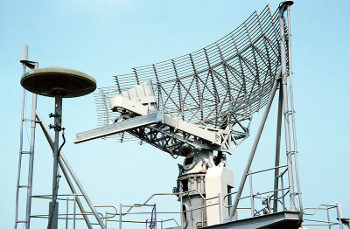
SPS-49 air search radar antenna aboard the nuclear-powered aircraft carrier USS Abraham Lincoln
Once you have your antenna, you're faced with a reality of physics. Since the intensity of an electromagnetic wave
decreases as the square of the distance from the source, you're faced with the fact that the intensity of your echo signal is reduced by r
4, where r is the target range. Why r
4? The signal reaching the target is reduced by r
2, and whatever signal reflected back to you is further reduced by r
2. Multiplication of these two factors gives r
4. This assumes, of course, that all your signal is reflected back. It's the goal of
stealth technology that none of the signal be reflected back. This is done by building aircraft from radar absorbent or transparent materials arranged in
convex geometrical shapes that reflect signals
diffusely and not
specularly (like a mirror).
Now that you've acquired a signal in a particular direction, the task is to determine its range. On paper, this is easy. You know the
speed of light. Just measure the time delay for the return signal. The problem, of course, is that the speed of light is very fast (299,792,458 meters per second in
vacuum). So fast, that it travels about 300 meters in a microsecond. However, if you're able to resolve nanoseconds, this is 30 centimeters, or just ten cycles of a 10 GHz signal. Such time resolution was difficult in the early days of radar; but today, when computers run at GHz rates, the electronics are not that difficult.
Stealth is not the only way to avoid radar detection. The other is
electronic countermeasures (ECM), which involve jamming the radar signal with extraneous signals that you generate. This task is made a little easier by the fact that any signal you generate is much stronger than the radar return echo from your craft. You can't just jam the radar return signal with an overpoweringly loud transmission. In that case, you would just be broadcasting your location. What you need to do is transmit random return echoes that confuse rangefinding. This become complicated, since the radar signals may be phased, as in monopulse, or they may be coded. When I used to subscribe to
microwave journals, about half of the ads were for ECM components and systems.
These many years of radar research have given a scientific dividend in the form of
weather radar systems (for which I did some computer modeling many years ago); and
Lidar, the laser variant of radar. Lidar was used recently to generate a highly accurate
topographic map of our
moon.[2] This new topographic map greatly expands our knowledge of lunar terrain, since many craters, especially in polar regions, have areas that are permanently shadowed and are not observed visually.
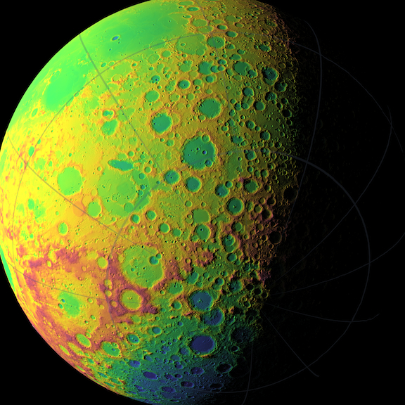
LOLA topographic map of the moon's southern hemisphere. The false colors indicate elevation: red areas are highest and blue lowest. (Figure: NASA/GSFC/MIT/SVS)
A team from
NASA's Goddard Space Flight Center in
Greenbelt, Maryland, presented their Lidar map of the moon at the
2010 Fall Meeting of the American Geophysical Union, December 13-17, 2010, in
San Francisco.[3] Lidar, of course, is radar that uses the optical portion of the
electromagnetic spectrum. Lidar has the advantage, at least in the airless environment of the moon, of achieving very good positional accuracy with a small emitter. The NASA
Lunar Orbiter Laser Altimeter (LOLA) splits a
laser beam into five separate beams that propagate to the lunar surface. The transit time of the return light gives the distance to the lunar surface, and when the spacecraft's orbit is taken into account, it gives the surface topography. The reason for having five beams is that the beam pattern gives additional data about slope. Additionally, the spreading of the beams reveals surface roughness, and the intensity of the light echo reveals the surface
reflectance.
The Lidar measurements performed over the course of the last year have produced three billion data points, and the experiment is expected to continue for another two years. The Lidar mapping has improved positional accuracy considerably over previous measurements, from kilometers down to a few tens of meters. The vertical accuracy of the map is about a meter. Previous maps had about a mile between data points. LOLA's data points are about 57 meters (187 feet) apart. This mapping has yielded at least one surprise.
Shackleton crater was found to have slopes of 36 degrees over several kilometers, which is perilous terrain, to say the least.
Geophysics seems to be doing well. The program booklet for the 2010 Fall Meeting of the American Geophysical Union, which contains titles and authors of papers, but not abstracts, was 560 pages![3]
References:
- Verfahren zur Bestimmung der Entfernung von metallischen Gegenständen (Schiffen o. dgl.), deren Gegenwart durch das Verfahren nach Patent 16556 festgestellt wird.
- Nancy N. Jones and Bill Steigerwald, "NASA's LRO creating unprecedented topographic map of moon," Goddard Space Flight Center Press Release No. 10-114.
- Scientific Program of the 2010 Fall Meeting of the American Geophysical Union (7.8 MB PDF File, 560 pages).
- History of Radar Page on Wikipedia.
- "Einstein Right Again," This Blog, July 15, 2008. Describes the pre-discovery observation of pulsars by US Air Force Sergeant, Charles Schisler, at a Ballistic Missile Early Warning System (BMEWS) system site at Clear Air Force Station, Alaska.
Permanent Link to this article
Linked Keywords: Radar; klystron; radio; Heinrich Hertz; electrical conductor; Alexander Popov; physicist; electrical engineer; Baltic Sea; Christian Hülsmeyer; Germany; US Navy; Potomac River; World War II; Britain; Robert Watson Watt; Chain Home; Pearl Harbor; SCR-270 Radar; mast radiator; vertical dipole; parabolic reflector; wavelength; dB; horn reflector; helical antenna; resonator; monopulse radar; Naval Research Laboratory; polarization; SPS-49 air search radar; USS Abraham Lincoln; inverse-square law; stealth technology; convex; diffuse reflection; specular reflection; speed of light; vacuum; electronic countermeasures; microwave; weather radar; Lidar; topographic map; moon; NASA; Goddard Space Flight Center; Greenbelt, Maryland; 2010 Fall Meeting of the American Geophysical Union; San Francisco; electromagnetic spectrum; Lunar Reconnaissance Orbiter; LOLA; laser; reflectance; Shackleton crater; Geophysics; pulsar; Ballistic Missile Early Warning System; BMEWS; Clear Air Force Station; Alaska.